
Rangkaian optocoupler relay untuk esp32 dan esp8266 YouTube
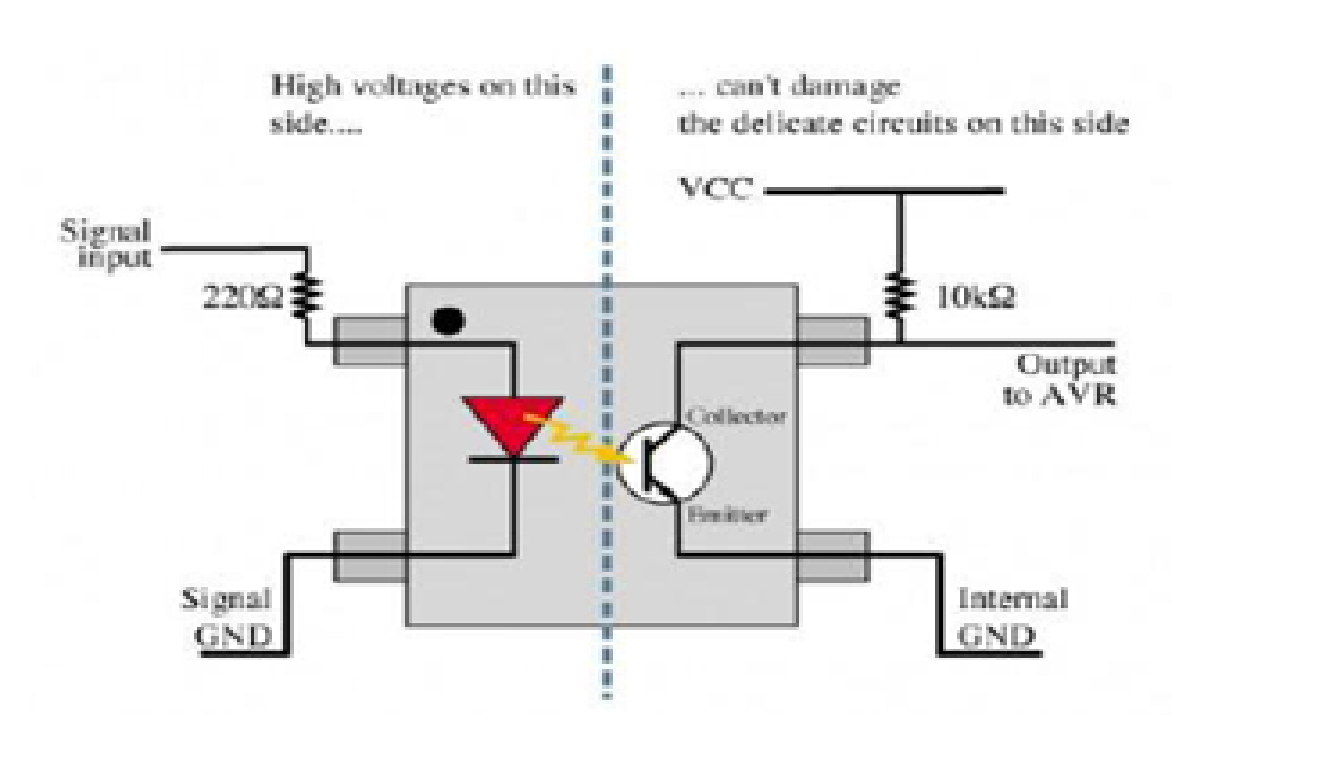
PC817 Photocoupler has a transistor which is controlled based on light (photon). So this IC basically has an IR (infrared) LED and a photo-transistor inside it. When the IR LED is powered the light from it falls on the transistor and it conducts. The arrangement and pinouts of the IR LED and the photo-transistor is shown below.
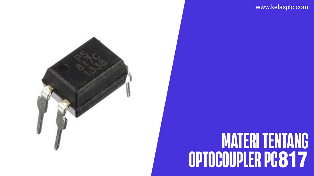
Apa Itu Optocoupler PC817 Pinout, Spesifikasi dan Penggunaanya
The pin configuration of PC817 Optocoupler is shown below, This IC includes 4 pins like 2 input pins and 2 output pins where each pin and its functionality is discussed below. PC817 IC Pin Diagram. Pin1 (Anode): In the optocoupler IC, this is an Anode pin of infrared LED (Tx). This pin provides a logical input signal toward the internal IR.

PC817 Optocoupler Datasheet, Pinout, Circuits, Arduino Examples Easybom
The PC817 optocoupler operates quite simply, although different devices have different requirements when using it. The optocoupler requires a current-limiting resistor on the input side, but we must fix the logic output pin through the power pin at the output. The generation of the infrared signal causes a shift in the current flow, which.
Pc817 Optocoupler Circuit everythingmzaer
Optocouplers also called photocouplers & opto isolators, they are IC type looking components available from 4 pins to many numbers of pins, they are mostly used for isolating of two circuits from each other. PC817 is a commonly used Optocoupler, it contains one IR LED and one photo transistor in its package. Its working is simple, when a used.

Optocoupler Isolation Board PC817 for PLC Arduino Raspberry Pi 4Ch Rytech Indonesia
PC816, PC817, LTV817, K847PH adalah beberapa optocoupler berbasis foto-transistor yang banyak digunakan. Foto - Opto-coupler berbasis transistor digunakan dalam isolasi terkait rangkaian DC.. Selanjutnya kita akan melihat pengontrolan rangkaian AC menggunakan rangkaian DC. Optocoupler untuk Mengontrol Rangkaian AC menggunakan tegangan DC:
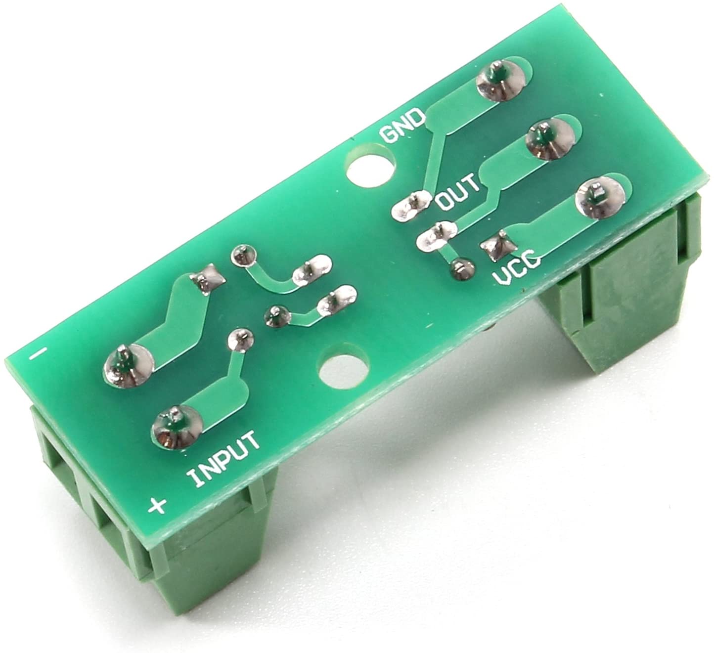
PC817 Optocoupler Isolation 3.3V 5V, 12V, 24V
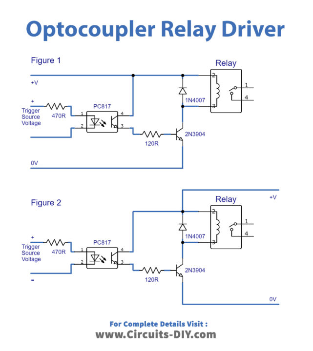
Fungsi optocoupler pada rangkaian elektronik biasa nya di gunakan untuk control switch seperti relay. biasa nya juga di gunakan sebagai conversi tegangan 12v ke 5v.. Kontaktor, dan lain lain. Contoh komponen yang termasuk sebagai optocoupler adalah ic 4n25, 4n25, MOC3021, PC817 dan lain-lain. Setidak nya komponen-komponen optocoupler ini.

PC817 Optocoupler Datasheet, Pinout, Circuits, Arduino Examples Easybom
PC817 Overview. The PC817X series optocoupler IC is comprised of an IRED (Infrared Emitting Diode, or IR LED) and a phototransistor optically coupled to it. It functions as the inner phototransistor conducts when receiving the IR LED's emitting light. These two parts are not hard-electrically connected; thus, it provides convenient optical noise isolation compared with using resistors and.
Pc817 Optocoupler Circuit Arduino
PC123 Optocoupler Introduction. PC123optocoupler is a type of optocoupler that includes an IRED optically connected to the phototransistor. It's a 4-pin DIP with wide-lead spacing and SMT gullwing lead-form. Its input-output isolation voltage (RMS) is 5.0kV. CTR is between 50% and 400% with a 5mA input current. Today, easybom will introduce the.
Pc817 Optocoupler Circuit Diagram
1. This tutorial gives an introduction to the HY-M154 / 817 optocoupler module. Moreover, a simple application is programmed that shows how to wire and how to program an Arduino when working with the module. In this tutorial, the module is used as an "digital input board". If you want to use the module as "digital output board", have a.

Cara kerja Optocoupler YouTube
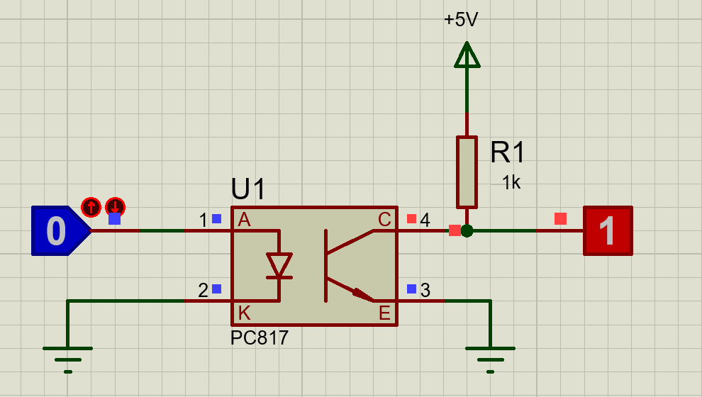
How to configure and use optocoupler in proteus professional to control an SPDT relay connected to a bulb. Optocoupler used in this simulation is PC817.Music.

Rangkaian test componen pc817 optocoupler YouTube
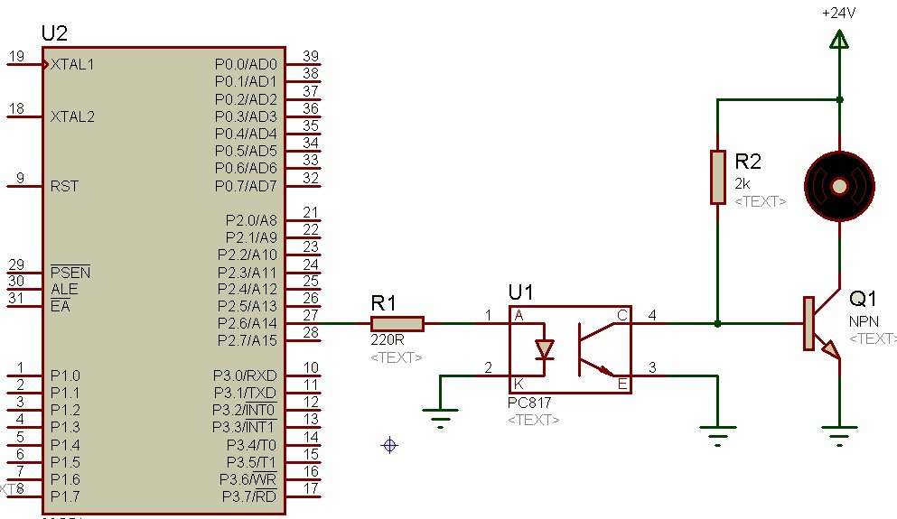
Proper usage of PC817 Optocoupler. I'm creating a logic based circuit and below is my schematic. The circuit first steps down a 24 VDC input to about 3.7 VDC using a 150 kΩ resistance and a 5.1 V Zener diode. This 3.7 VDC is fed to the input of optocoupler PC817 pin 1 and 2. On the output, I wanted to read the high and low through an Arduino.

Electrical Proper usage of PC817 Optocoupler Valuable Tech Notes
PC817 is a 4 Pin optocoupler, consists of an Infrared Emitting Diode (IRED) & photo transistor, which enables it optically connected but electrically insulated. Inrared Emitting Diode is connected to first two Pins and if we apply power to it, then IR waves are emitted from this diode, which makes the photo transistor forward biased.

PC817 Optocoupler Datasheet, Pinout, Circuits, Arduino Examples Easybom
Pada rangkaian optocoupler PC817, IR mendapatkan sinyal noise dari satu bagian dan mentransmisikannya ke bagian lain menggunakan sinyal IR sehingga bekerja berdasarkan desain rangkaian. IC PC817 terdiri dari LED dan phototransistor yang terhubung bersama secara optik. Sinyal dapat ditransmisikan secara optik antara i/p dan sisi output daya.
PC817 Optocoupler pinout, working and Example with Arduino (2022)
It is a 4 optocoupler module. On the input side of the optocoupler all the grounds are tied together. doesn't this have the possibility to cause ground loops?? On the output side of the optocoupler, it seems like the jumper is there to connect the output ground with that of the input ground doesn't this defeat the purpose!
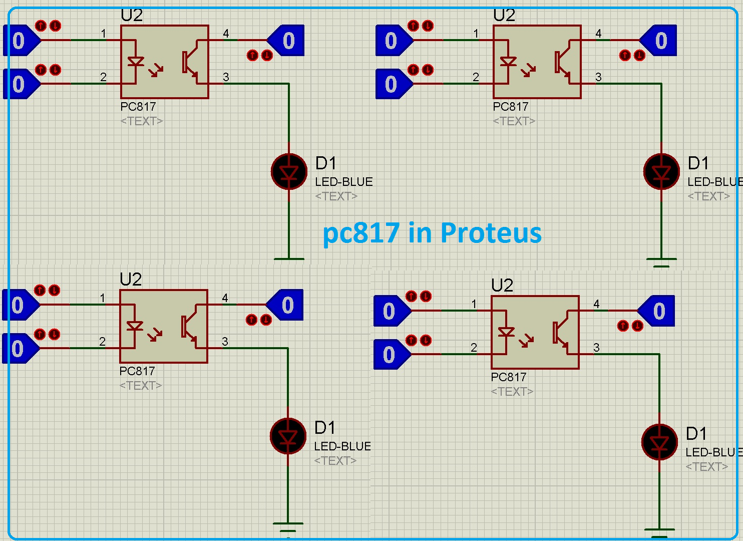
PC817 optocoupler in proteus
PC817 Description. PC817 Optocoupler also called photocouplers & optoisolators, an IC kind of seeing tools available from 4 pins to many numbers of pins, they are commonly used for the separation of two circuits from each other. It consists of Infrared Emitting Diode (IRED). This IRED is coupled to a photo transistor optically and not electrically.
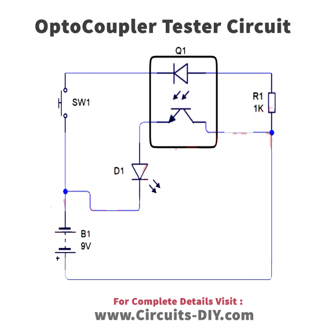
PC817 Optocoupler Tester Circuit
The PC817 is a commonly used linear optocoupler. It is often used as a coupling device in various functional circuits that require more precision. It has the effect of completely isolating the upper and lower circuits without affecting each other. Figure 1. Optocoupler PC817 pin diagram and internal circuit. Figure 2.
