Plug Connector Vector Icon 355774 Vector Art at Vecteezy
1 Answer. That is a receptacle for a barrel connector. The symbol is supposed to imply circuit functionality. The following is not a standard symbol (don't use it!), but it should demonstrate the connection: When you insert the connector into the receptacle, the center of the connector contacts the wide pin (the rectangle).
Pengertian Konektor Beserta Fungsi dan JenisJenis Konektor [Lengkap]
All connectors shown in the KiCad symbol library "conn" need an overhaul to conform to IEC 60617. For instance take a look at the symbol for a D-susb 9 (DB9) connector. The graphic symbol shows unfilled circles and the outline depicts the characteristic D shape. An unfilled circle is the symbol for a terminal but in this case I presume this is supposed to be the symbol for a socket/female.
electrical outlet diagram symbols Wiring Diagram and Schematics
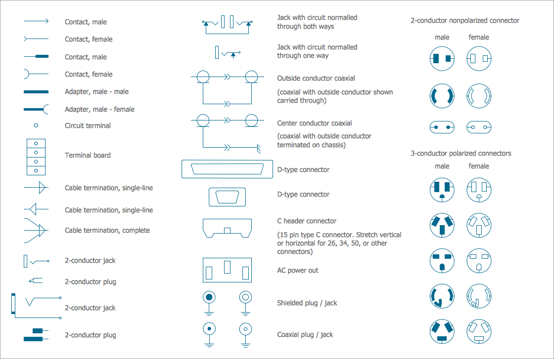
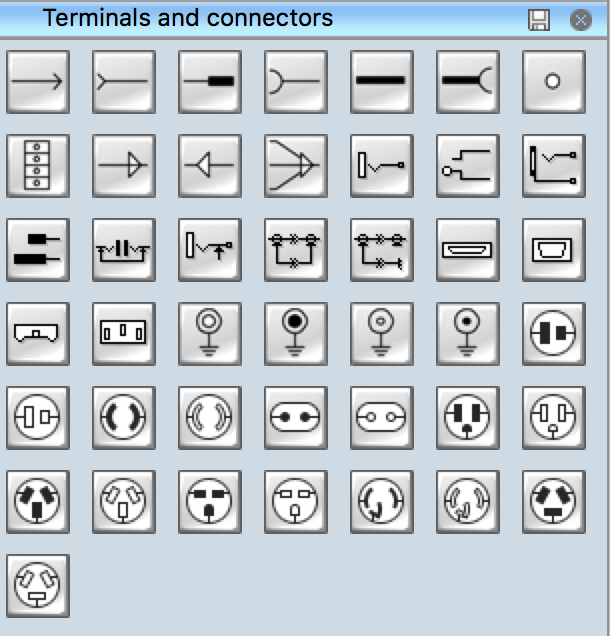
The vector stencils library "Terminals and connectors" contains 43 element symbols of terminals, connectors, plugs, polarized connectors, jacks, coaxial cables, and conductors. Use it for drawing the wiring diagrams, electrical layouts, electronic schematics, and circuit diagrams. "An electrical connector is an electro-mechanical device for joining electrical circuits as an interface using a.

Electrical Schematic Symbol Connectors AutoCAD Free CAD Block Symbol And CAD Drawing
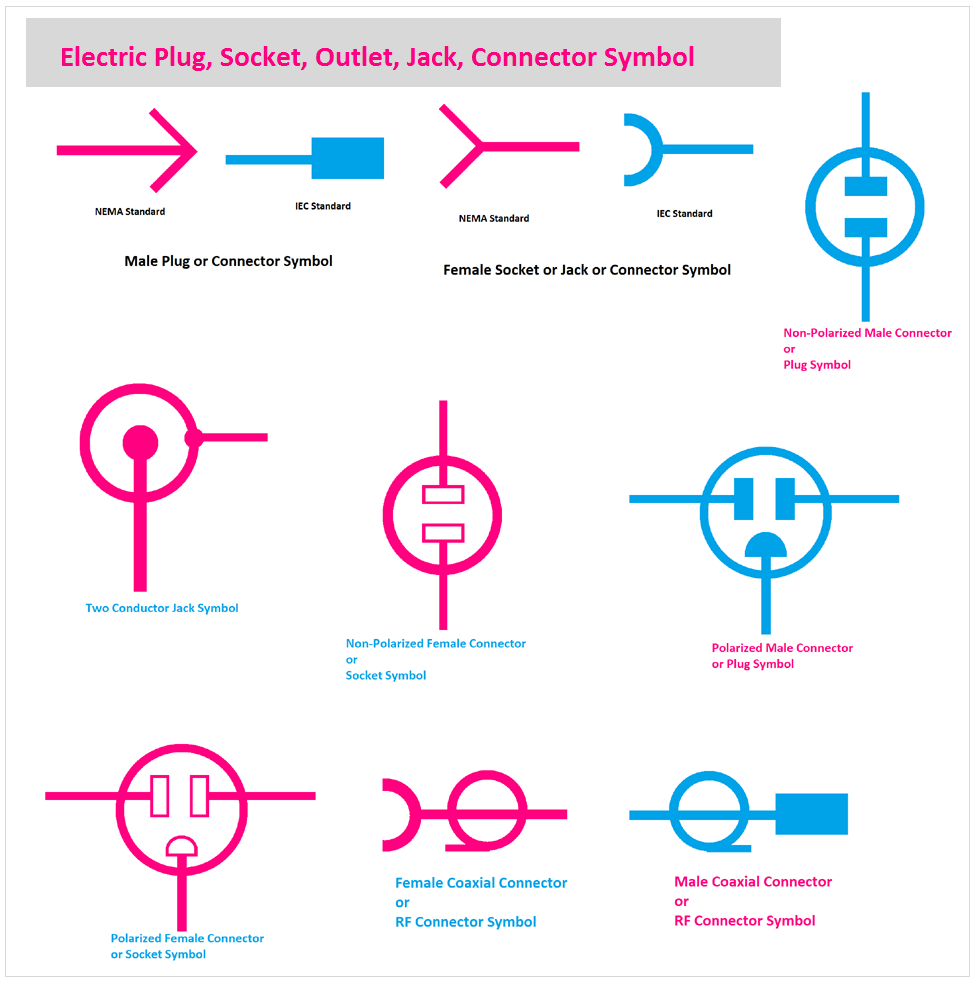
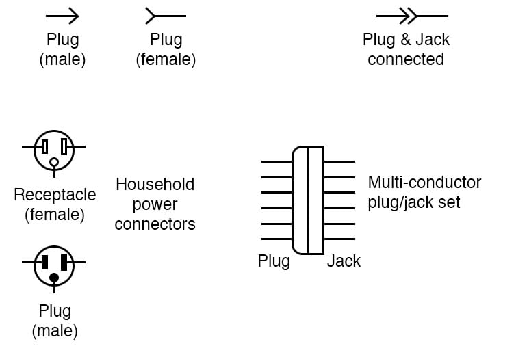
An electrical connector, is an electro-mechanical device used to join electrical terminations and create an electrical circuit. Electrical connectors consist of plugs (male-ended) and jacks (female-ended). The connection may be temporary, as for portable equipment, require a tool for assembly and removal, or serve as a permanent electrical joint between two wires or devices.
26.
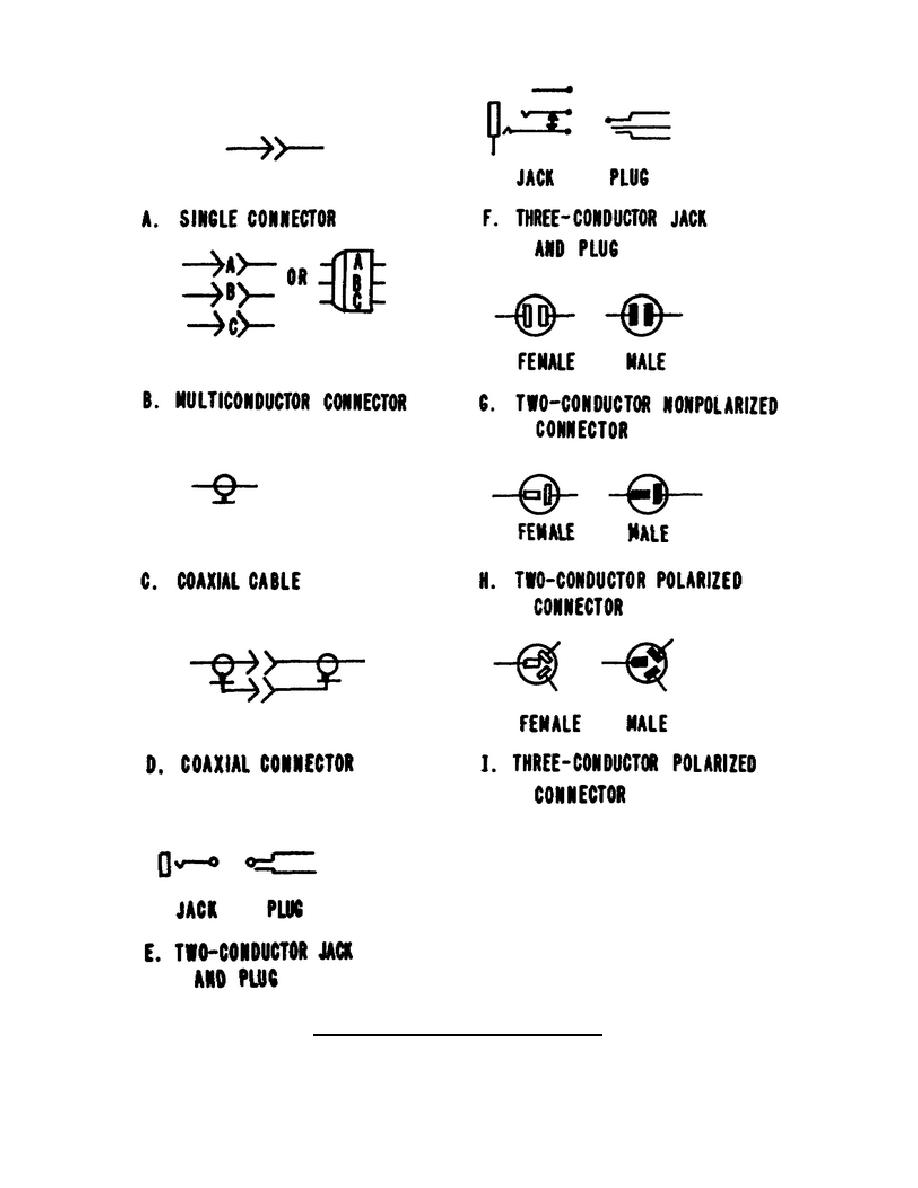
Figure 314. Connector symbols
Electrical symbols & electronic circuit symbols of schematic diagram - resistor, capacitor, inductor, relay, switch, wire, ground, diode, LED, transistor, power.

Grupo De Símbolos Do Esquema De Circuito Bonde E Eletrônico De Conectores Bondes, De Soquetes
Electrical & Electronic Symbols www.electrical-symbols.com Electrical Connectors Symbols, Sockets, Plugs, Jack. [ Go to Website ] 2/3 All Electrical & Electronic Symbols in https://www.electrical-symbols.com
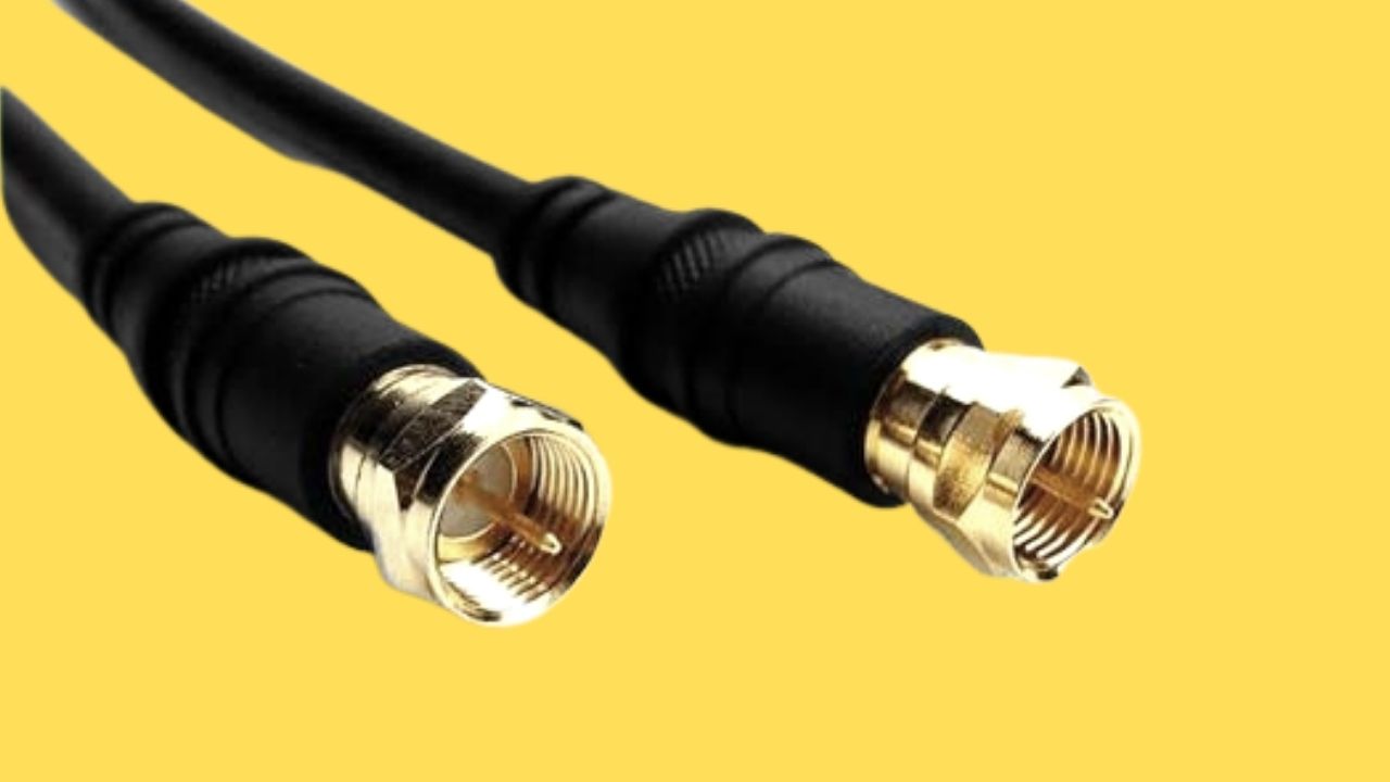
Cable Connector Symbols
A plant diagram is undoubtedly one of the most important documents in a manufacturing plant. We'll start our schematic reading course with the simplest item we can find in an electrical closet - the cable connector (ZUG). Connectors are a very important element in almost every electrical installation and control and measurement equipment. They provide […]
Electrical Symbols, Electrical Diagram Symbols
Basic electrical and electronic graphical symbols called Schematic Symbols are commonly used within circuit diagrams, schematics and computer aided drawing packages to identify the position of individual components and elements within a circuit. Graphical symbols not only identify a components position but the type of electrical element too.

Wiring Diagram Symbols Connector Doctor Heck
Electrical Symbols — Terminals and Connectors. An electrical connector, is an electro-mechanical device used to join electrical terminations and create an electrical circuit. Electrical connectors consist of plugs (male-ended) and jacks (female-ended). The connection may be temporary, as for portable equipment, require a tool for assembly and.
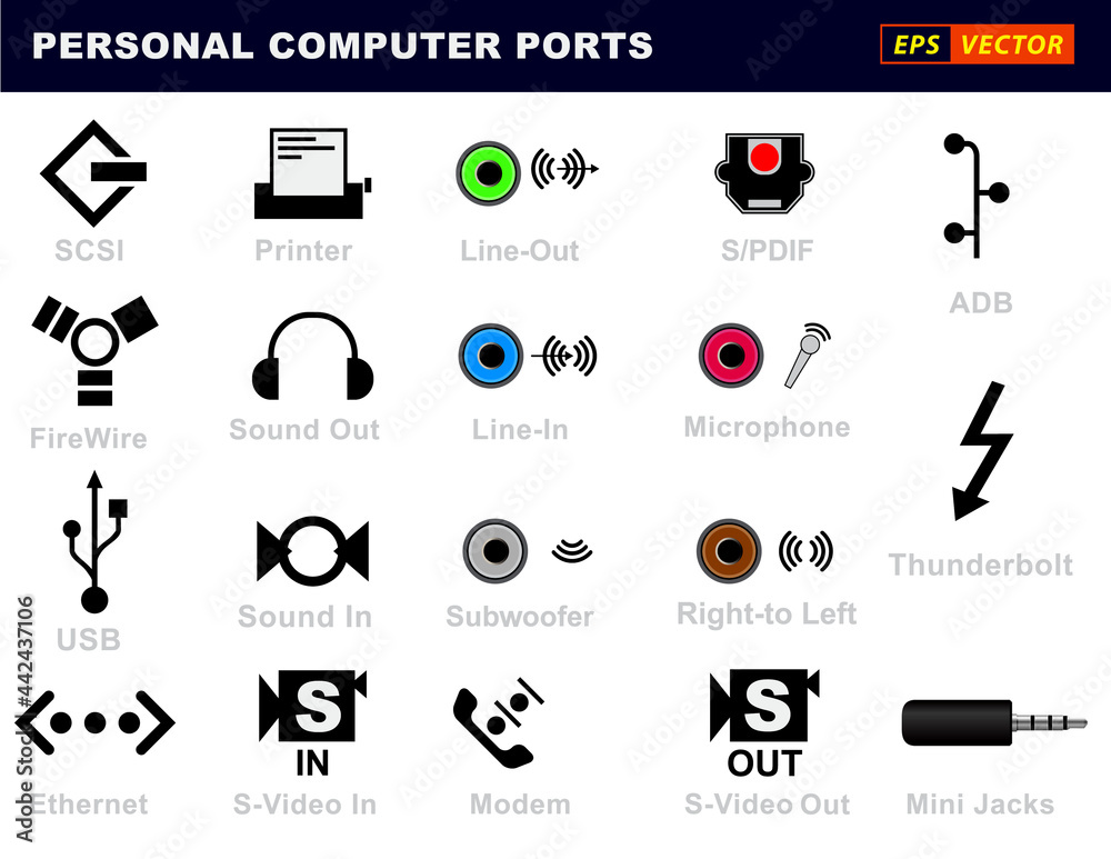
set of realistic personal computer ports connectors or usb universal connector symbols or
60 - Voltage or Current Balance Relay. 62 - Time-Delay Stopping or Opening Relay. 63 - Pressure Switch. 64 - Ground Detector Relay. 65 - Governor. 66 - Notching or jogging device. 67 - AC Directional Overcurrent Relay. 68 - Blocking or "out of step" Relay. 69 - Permissive Control Device.

Wiring Diagram Symbols Connector Doctor Heck
Standard electrical IEC symbols also known as IEC 60617 (British Standard BS 3939) used to represent various devices including pilot lights, relays, timers and switches for usage in electrical schematic diagrams. Tip: Streamline your electrical design process and improve your workflow with Capital Electra X.
√ Konektor Pengertian, Jenis, Fungsi dan Gambarnya
Electronic symbol. An electronic symbol is a pictogram used to represent various electrical and electronic devices or functions, such as wires, batteries, resistors, and transistors, in a schematic diagram of an electrical or electronic circuit. These symbols are largely standardized internationally today, but may vary from country to country.

Electrical Connectors Symbols, Sockets, Plugs, Jack Electrical symbols, Connectors, Plugs
The symbol for a connector is typically just a rectangle with a line of pins on it. The specifics of the symbol don't really matter. The only thing that matters is that you have the right number of pins on it and that the pin names on the symbol match the pin names in the footprint. a) You can use the KI-CAD symbol editor to make the connector.

기호 배선도 전기 커넥터 직류, 잭, 기타, 각도 png PNGEgg
1. Graphic symbols of substation elements. Substations are usually presented using various elements (e.g. power transformers, circuit breakers, isolators, instrument transformers CTs, VTs etc.) by their graphic symbols in the connection schemes. Symbols of the most important equipment in transformer substation are given below.
Wiring Diagram Connector Symbols
The following terminals and connectors symbols present some standard terminal symbols and connector symbols for logical and digital circuit drawings such as M/F contact, adapter, circuit terminal, terminal board, 2-conductor jack, normal jacks, coaxial outside symbol, etc. . They also show some connector symbols such as large D connector, small D connector, C header connector, F/M 2-conductor.
Electrical Symbols Electrical Schematic Symbols
Wires and Connections. Older electrical schematics showed connecting wires crossing, while non-connecting wires " jumped " over each other with little half-circle marks. Newer electrical schematics show connecting wires joining with a dot, while non-connecting wires cross with no dot. However, some people still use the older convention of.
