
Cara menambah rangkaian Bias Servo pada SOCL506 YouTube
Ini adalah cara memasang rangkaian bias servo pada SOCL 506.Di video kali ini temanya masih sama yaitu tentang modif memodif.. Rangkaia.
The control circuit of twophase servo motor Control_Circuit Circuit Diagram
Rangkaian Bias Servo Berfungsi Sebagai Sensor Untuk Transistor Pre Driver ,Dan memberi Perintah Untuk Menaikan atau Menurunkan Nilai Bias Pada Transistor Tersebut,agar Pada rangkaian Final Transistor Bisa di control Bianya agar tidak melebihi dan mengakibatkan Transistor Final pada sebuah amplifier Jebol atau terbakar.

Membuat BIAS SERVO AMPLIFIER terbaik dan paling stabil YouTube
Bias servo driver socl 506 - cara kerja bias servo untuk mengontrol tegangan bias agar tetap setabil dalam suhu panas, transistor mje340 sebagai sensor untuk.

Mengendalikan Motor Servo Sketch dan Project Program Arduino 📘 Bintan News
Mehdi, one of the students explained afterwards: "The New York trip was an amazing opportunity to visit a beautiful city and at the same time have the chance to be at the beating heart of one of the world's financial centres.It was unforgettable to witness a real-life IPO.

fungsi dan carakerja bias servo YouTube
Introduction. Understand a complex world, anticipate developments and transform it sustainably. The Master in Management, Grande Ecole programme is open to students with a non-French bachelor degree. It is taught on our campuses in France (Lille, Paris and Sophia Antipolis), Brazil (Belo Horizonte), China (Suzhou), USA (Raleigh), and in South.

Bias servo for class AB Page 2 diyAudio
Pada skema socl 504 memiliki variable DCo agar dapat disesuaikan keluaran dco sampai 0 volt. Berikut ini merupakan keterangan gambar skema berdasarkan daftar komponen:. Mungkin di update selanjutnya yaitu dengan menggunakan bias servo agar bias bisa di setting.

Bias servo for class AB Page 2 diyAudio
Cara Kerja Rangkaian Bias Servo - YouTube 0:00 / 10:27 Cara Kerja Rangkaian Bias Servo By Audio Ngawi 63.3K subscribers Subscribe 52 4.8K views 2 years ago Halo mbah apa kabar? Di video.

Skema Rangkaian Tester Penggerak Motor Servo Sederhana Foxify
bias servo adalah sbuah skema pengatur rendah & tinggi nya bias pada kit amplifier, Bias servo ini sering disebut juga VBE Multiplier ,terdiri dari 1 buah transistor , 2 buah resistor ,1 buah Capasitor & 1 buah variabel/trimpot, untuk cara merangkai nya silahkan sobat perhatikan gambar skema Bias Servo di bawah ini : Fungsi Bias Servo

trimpotbiasservo CARA BUAT TRIMPOT BIAS SERVO YouTube
Dari skema ini nampak bahwa power ampli menggunakan prinsip OCL kelas AB dengan penguat differensial sebagai penguat awal ( T1 dan T2 ), Penguat tegangan ( T4 ), servo bias driver ( T6 ), Over Current Protection ( T6 dan T7 ), hingga driver merangkap final power ( T9, T10, T11, T12 ). Lihat ukuran 1709 Pixel di sini.

Penjelasan Cara Kerja Bias servo pada Power Amplifier YouTube
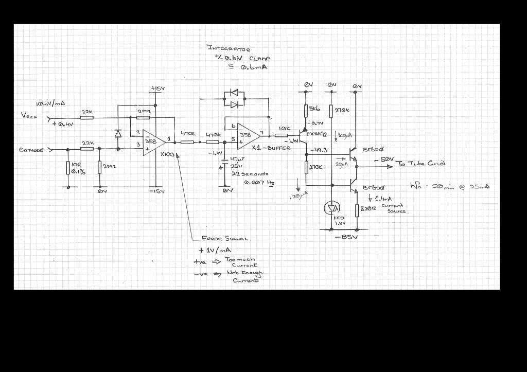
ALL servos work the same basic way: a sense resistor in series with the cathodes of the output tube (s) is a current-to-voltage converter; tapping its rapidly varying (and low level, due it being to a low value resistor) signal, and running that into something that'll time-average it to a near-DC voltage.

Cara Pasang Bias Servo Pada Driver SOCL BLOGKAMARKU
The DC-Servo controls ultra-low-frequency signals (all those below 1 Hz) so that they can't reach your speakers. Which means you can, if you have to, play warped records and still hear good sound. Power output is a comfortable 65 watts per channel both channels driven into 8 ohms, all this from an OCL (Output Capacitor-less) true complementary.

Bias servo for class AB diyAudio
#1 Schematics of 4 channel servo bias board for KT88/6550 PP output stages. C7 should be a good quality cap such as film and is 100V. C8 is low voltage 10uF ceramic. POWERUP should be a 0V for 25s or so until the cathode emission starts and then pulled to -10v or greater to make the bias active.
Yet Another Output Tube BIAS Servo Schematic from DIYAudio.ru diyAudio
Penjelasan Cara Kerja Bias servo pada Power AmplifierPembahasan driver power ini Part 1 https://youtu.be/_iiqLXNoKigPart 2 https://youtu.be/9nubjUwfX7QPart 3.

Bias servo for class AB Page 2 diyAudio
2 - Inverting DC Servo. In Figure 2, there is an amplifier circuit (shown simply as 'Amp') and a DC servo circuit (shown as U1). If the amplifier shows any sign of DC at the output, this is integrated by U1, and that signal is applied to the amp's input to correct the offset.. and this can't force enough current through the bias network (R3.
MERAKIT MODUL DCO SERVO/AUTOMATIC DC OFSETT POWER AMPLIFIER YouTube
PCB LAYOUT SOCL504 TEF + PROTECTOR. Elcircuit will share the TEF version of the SOCL504 power amplifier PCB layout file and is equipped with final transistors and speaker protectors. This amplifier can be supplied with a minimum power supply voltage of 45VDC - 90VDC asymmetrical, and this SOCL 504 amplifier can output a large power of up to.

Skema Bias Servo & Fungsi nya Mas ikhin Web'Blogs
SEKEMA BIAS SERVO DAN CARA MEMBUAT BIAS SERVO Chut tigawe 2.38K subscribers Subscribe 6.4K views 3 years ago Merancang bias servo di amplifier 400 watt Sangat mudah untuk mengesetvtr.
